I am reaching out to seek advice regarding a technical issue we encountered while setting up a Motus CTT SensorStation in a location which is remote, and our access is limited to trips every 2-3 months, with about 1-2 hours on-site per visit.
Setup Background:
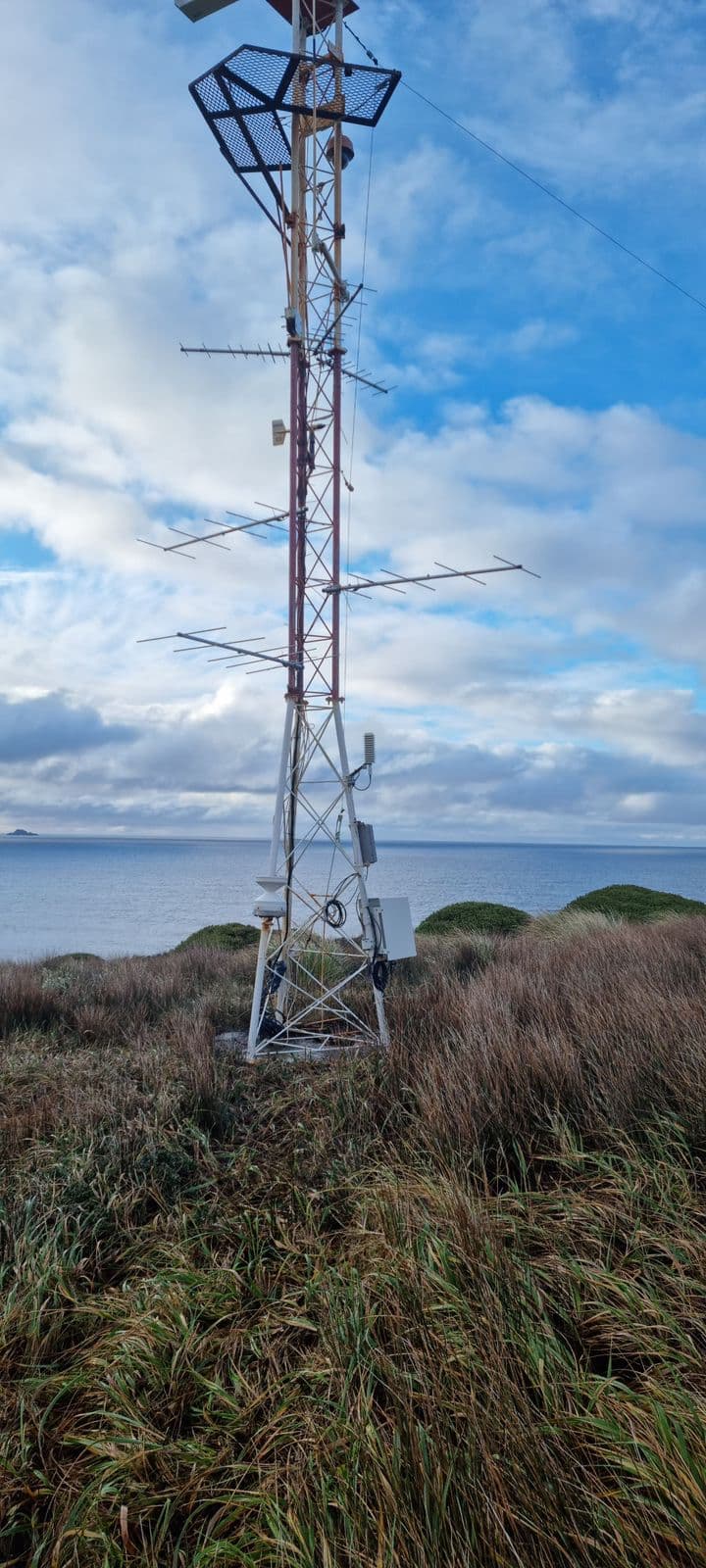
We are mounting the antennas on a existing steel tower and using power from a generator, which operates continuously. In August, during an initial trip, we installed the antennas and connected their coaxial cables, but leaving the free ends wrapped in plastic bags for protection.
Issue Encountered:
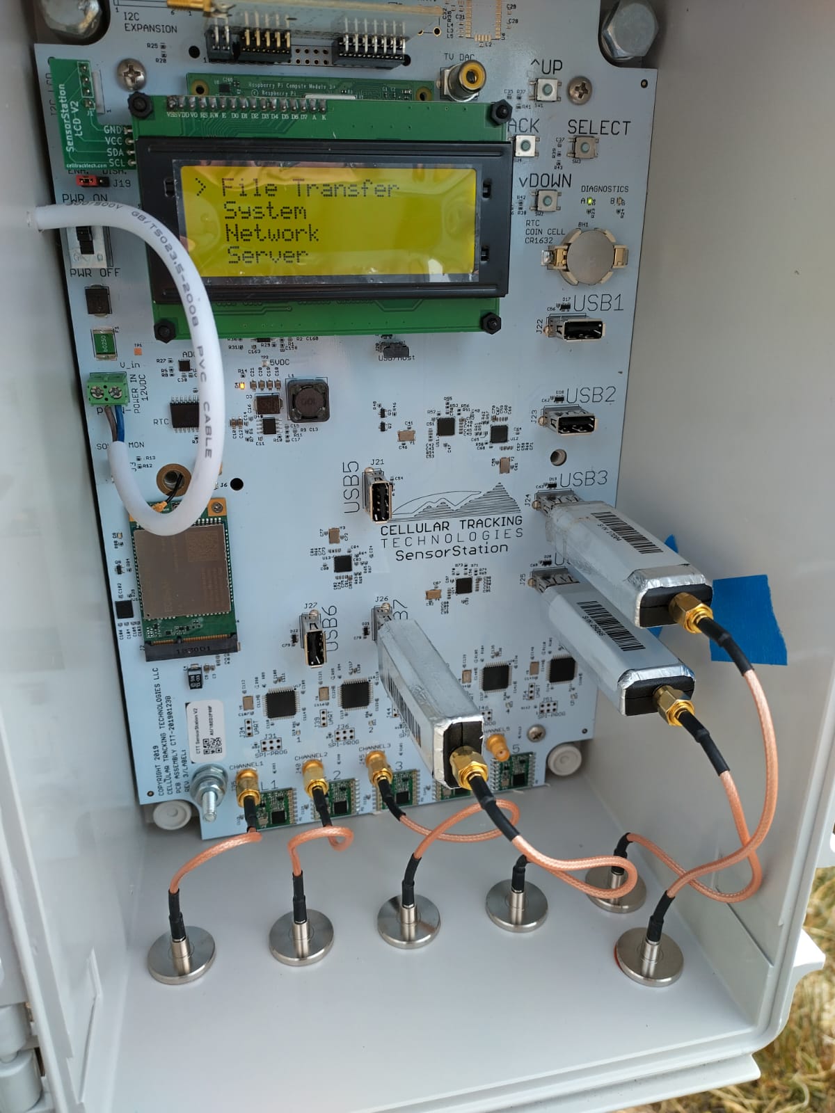
On a recent follow-up trip, we installed the SensorStation and connected all components. Initially, the receiver powered on correctly. However, when we connected the first coaxial cable, this immediately caused a power outage. After resetting the power, we tested the same cable connection again, which led to a louder noise (similar to a small explosion), another power outage, and left a black mark related to this power outage on the electric converter located on the side of the box. The receiver stopped functioning completely after this event.
Possible Causes Considered:
Could leaving the coaxial cables connected to the antennas for three months have led to corrosion, thereby causing the short circuit?
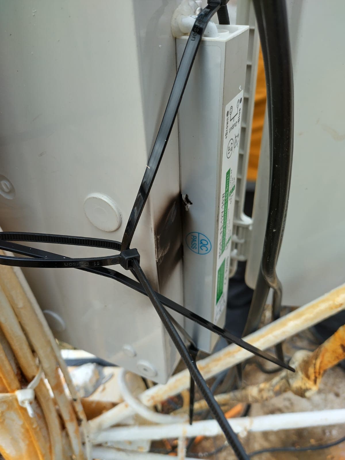
We also noticed that the input cable to the inverter had exposed wires at the connection point (the protective covering did not fully cover the cables).
Major questions:
-Could corroded coaxial chords have caused this type of power issue? I am not sure if those can alter the electrical system of the receiver. Has anyone experienced similar issues with the converter or coaxial cable connections causing power interruptions or short circuits?
We will replace the power inverter, but how could we secure the system before connecting to know if it is safe to turn on?
Any insights or suggestions would be greatly appreciated as we plan our next steps. I look forward to hearing from anyone who might have experienced a similar situation or has advice on how to proceed.
Thank you for your help.
Best regards,
Matías Troncoso-Villar
Cape Horn International Center (CHIC)
To me, this seems like a issue directly related to the 12V power supply you are using. How is the 120V input connected to the generator, is it plugged into an outlet? Also just to cover all bases, did you double check that the 12V output wires were connected to the correct +/- terminals on the board?
Hi Nick,
The power supply is 220 V, 60 Hz and is in a well-designed battery system. It supports a whole house and a lighthouse many years ago. I connected it to a extension and then plugged directly to the outlet, so it is a constant current source.
Yes, the wiring was OK (± related).
It is to notice that the Receiver was ON just before I touched the coaxial connector to the actual coaxial chord (pic bellow just minutes before I touched the bottom coaxial connection). It was a coaxial related issue, I can guess.
Was the explosion at the 12V inverter the only observed effect? Were there any other burn marks or explosions on the board or FunCube Dongles? I would imagine that if the problem was related to the coaxial connection, there would have been signs closer to that connection (blown up FunCubes, burn marks on the board or at other points of connection).
Also, you mentioned seeing exposed wire at the input to the power inverter. I think it’s more possible that water or something else made its way into the inverter and caused an internal short. This would explain the explosion occurring inside the inverter, rather than near the coax connection. More pictures of the power inverter and inside the board may be helpful if you have them!
The test that I would do is with coax not connected and power on the CTT receiver using a volt meter measure the voltage between the coax out shield and the shield connector on the CTT receiver. If there is a voltage reading you have a ground loop problem.If that is the problem the antenna tower is at a different ground potential than the generator supply. Just a guess at this point but an easy test.
I would agree with Glenn. There is something causing current to flow through the coax. There may also be problems with the power supply, as Nick suggests, but it does not explain why the event happened when you connected the coax.
@Nick.Haddad,
unfortunately, I don’t have any post-explosion pictures of the FunCube Dongles nor the mother board of the receiver. They are now in a different island than myself.
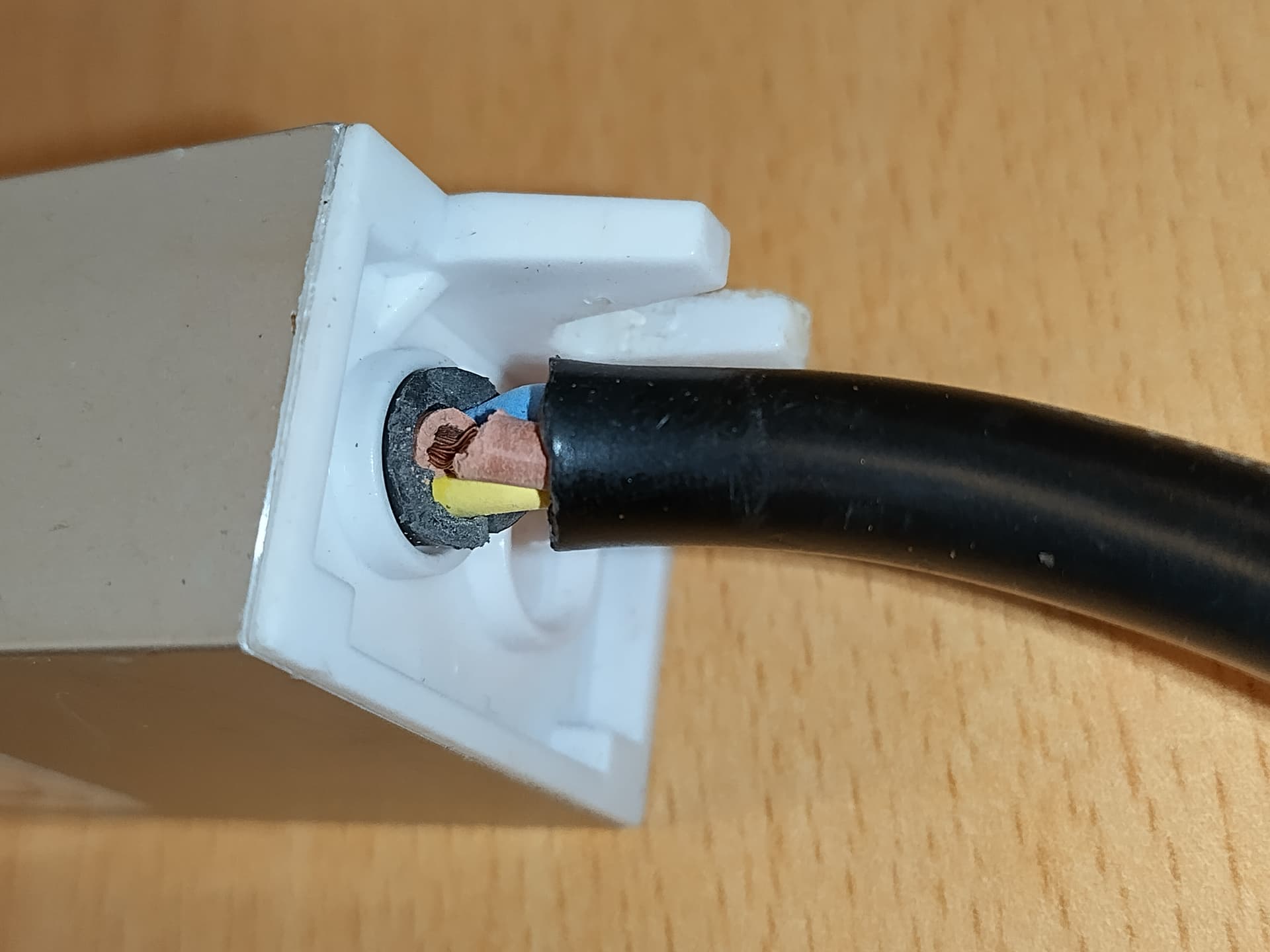
The exposed wire initially appeared as a clean cut in the INPUT side of the power inverter, but now it’s really broken:
This is my main thought directive, but it’s strange that it occurred the moment the coaxial made contact with the connector and not before.
@user949,
Thank you for the diagnostic guidance. I won’t be able to test until December-January, at which time I will have 6 new coax cables (just in case they were involved in the issue) and a replaced power inverted also.
@Pat_Lorch_SSRS,
Yes, it seems that everyone’s thinking is heading in that direction. Thank you
Exposed copper like that is definitely a no-go and most likely the cause of your short. Diagnostic testing with a multimeter is a great idea like Glenn and Pat are recommending. Replacing the inverter with a new one and doing that testing before attaching your coax cables will give you a sound answer.
I think it’s very possible that when connecting the coax cables, the whole station box moved slightly and caused wires to touch in the inverter that previously were not.
I did some testing with mt CTT receiver and power supply. The shield of coax is isolated form the input to the power supply or inverter as you call it. So there is no path for current to flow form coax shield to input AC power. As stated before look like the damaged ac input cable to the power supply was the problem. I think the CTT receiver is ok. Were are you located?
Glenn, I don’t know what you measured, but I have an SSv3 here and the sleeve of the 433 connectors is definitely connected to the station ground and the FCDs I have also connect the sleeve to the USB ground (but not connector shield). This means that the coax sleeve is connected both to the tower steel and the ground of the 12V circuit. Seems to me that connecting these causes a short. Use a voltmeter to measure the potential between the two before connecting…
It looks like what Matias calls an inverter is really a no-name 12V power supply made to drive LEDs. I’m pretty sure these must be isolated (have no direct connection between input and output) but given that it’s a no-name brand it’s worth checking with a multimeter (continuity check mode). The frayed cable may have shorted something but it doesn’t look like that to me to be honest. Verify that whatever power supply you use next has proper isolation between input and output. Also, do not bend electrical cables so tight, like the 12V going into the sensorstation box, leave a few cm so it’s a gradual bend.
Before you connect coax again measure the voltage (both AC and DC) between the coax sleeve and the 12V ground. Also measure between all 3 terminals of the generator (earth, neutral, line) and the tower steel (be careful with your fingers!!!): you should see more or less zero for earth and neutral and then 220V for line (could also be more or less zero if the gen output is not bonded to earth at all). In general you cannot assume that the generator neutral and earth are bonded or can be connected, plus someone could well have wired something incorrectly.