I am planning to build a MOTUS receiving tower, and I am currently in the process of sourcing the necessary components for the tower, aiming to keep costs as low as possible.
One of the components I am considering is the RTL-SDR v4 dongle for signal receiving. However, I am unsure if this particular model is supported by the SensorGnome software - the (still recently relased) v4 dongle does require different drivers than v3 due to some changes made to the circuitry, and most of SDR apps had to be updated to be compatible with v4. I have searched through the available documentation but have not found a definitive answer.
So, could you please confirm whether the RTL-SDR v4 dongle is compatible with the SensorGnome software, or it will be better to buy the v3 version, since it is still available?
I appreciate your time and look forward to your response.
Hi Jakub, I just made the changes to the Sensorgnome V2 software to support the rtl-sdr.com V4 dongle. I have not released this new version yet, but will do so in the coming days. In case I get delayed and you need it, just ping me, I’m trying to get some other things improved but can cut a release any time.
Note that the v4 dongle is not compatible with the current SensorStation software or the older Sensorgnome software. There are code changes necessary (and the version of the “driver” library that needs to be upgraded is a modified version of the official rtlsdr library, so it’s not just a matter of pulling the latest official version in).
Hope this helps!
NB: in preliminary tests I’m finding that the rtl-sdrs are performing as well as FCDs except at the long end of the range. This is an area of active investigation at the moment…
I read with full interest this sentence “NB: in preliminary tests I’m finding that the rtl-sdrs are performing as well as FCDs except at the long end of the range. This is an area of active investigation at the moment…”. It that also in a more noise environment?
René, I can’t say much about noisy environments because I don’t know that I can test that. I’m gearing up to be able to have others that have problem stations test.
I distinguish two types of noise: in-band and out-of-band. In-band noise means “stuff” that transmits at the same frequency as the tags, or on very close frequencies. So far I do not believe that the RTL-SDRs behave any differently from the FCDs. Then there’s out-of-band noise, which is outside of the frequency band that the SDR is tuned to and that should be rejected/ignored but ends up affecting the SDR due to the way radio stuff works. We have long hypothesized that strong out-of-band signals can desensitize or otherwise interfere with the RTL-SDR more than the FCD. The difficulty is how to test this.
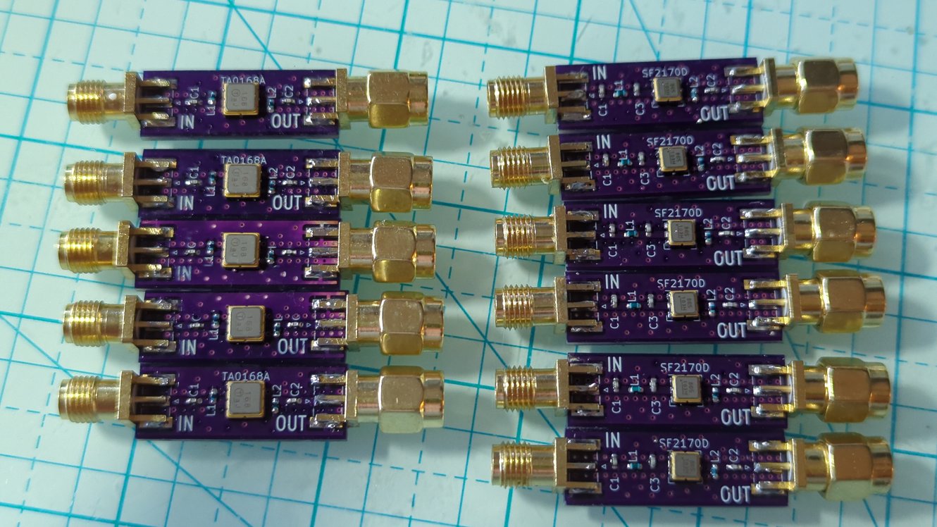
I made a dozen filters (SAW filters to be specific) that are highly selective for an 8Mhz band from 159-167Mhz. These should pretty much block out everything outside of this band. The downside is that they, like any component added, add a little bit of noise. Which brings up signal-to-noise. At the end of the day, the tag detection looks for 2.5ms long RF pulses which “stick up” from the noise floor by at least 6dB, i.e. they need to have an SNR (signal-to-noise ratio) of at least 6dB.
There is a solution to all this, which is to combine an LNA (low noise amplifier) with the filter. Long technical story… I’m in the process of sending some more PCBs to be made that will combine an LNA with the SAW filter and I’m crossing fingers that this will improve the SNR of the RTL-SDR to match the FCD. Of course nothing ever “just works”.
In my testing I have also seen that for signals that are not at the SNR limit the RTL-SDRs work slightly better than the FCDs in that a higher number of pulses get detected. The difference is quite small but it’s there. I’m not sure what that is due to. So overall I must say that I’m much more positive about the RTL-SDRs now than I was before. It is important, however, to get quality ones, like from rtl-sdr.com or nooelec. There is some more nuance, for example Adam tested a bunch, including a Nooelec one that uses an E4000 tuner (as opposed to the more common R820/R828/R860 tuners) and due to some software quirks it ended up being configured poorly and not performing well at all. This is easily fixable now that I understand the issue. Yes, it’s a deep rabbit hole…
So lots of work in progress, stay tuned! (pun intended)
Thorsten
NB: I have a small number of SAW filters that I’m happy to send out for testing. The test would need a station known to have lots of noise and not perform well, then adding the filter and seeing whether anything is improved or not. Ideally using a Sensorgnome with the V2 software as it provides a lot more stats. Please contact me if you’d like to try: I’ve been holding off on sending filters out so far because I want to make sure the testing effort is really worth it.
When dealing with noise antenna selection should also be considered. I use a type of antenna called LFA loop folded antenna for my weak signal VHF ham radio. I also use this antenna for the Motus system I have installed. LFA can reject 3db or more noise. Intemod is sell a 434MHZ LFA. Ones for 166.380 are harder to come by and have to be specially made. Innovantennas in England can make the 166.380 MHZ LFA antennas
I appreciate you going down the Rabbit Hole a bit. I spend a lot of time thinking about these things but do not have the know-how to test them.
We have a couple of mobile units that I bought some V4 RTL-SDRs for but we aren’t planning on deploying them for three weeks or so.
Thanks for all of your hard work and the explanations,
Levi
– The Motus Wildlife Tracking System (Motus) is an international collaborative research network that uses coordinated automated radio telemetry to facilitate research and education on the ecology and conservation of migratory animals. Motus is a program of Birds Canada in partnership with collaborating researchers and organizations. Learn more at — You received this message because you are subscribed to the Google Groups “Motus Wildlife Tracking System” group. To unsubscribe from this group and stop receiving emails from it, send an email to . To view this discussion on the web visit .
Indeed that is very interesting news Thorsten. You have my full attention. :)
My Pigeon Lake station ( SG-77BFRPI4B4A1) has had consistent very high levels of false Lotek pulses (>2 000 000/day), since it was brought online last year. All three antennas appear to be affected. Usually the hits are highest during the day then reduce to a couple 100/hr in the night, usually, but not consistently. It’s in a small lakeshore community, where ISP’s use cellular primarily.
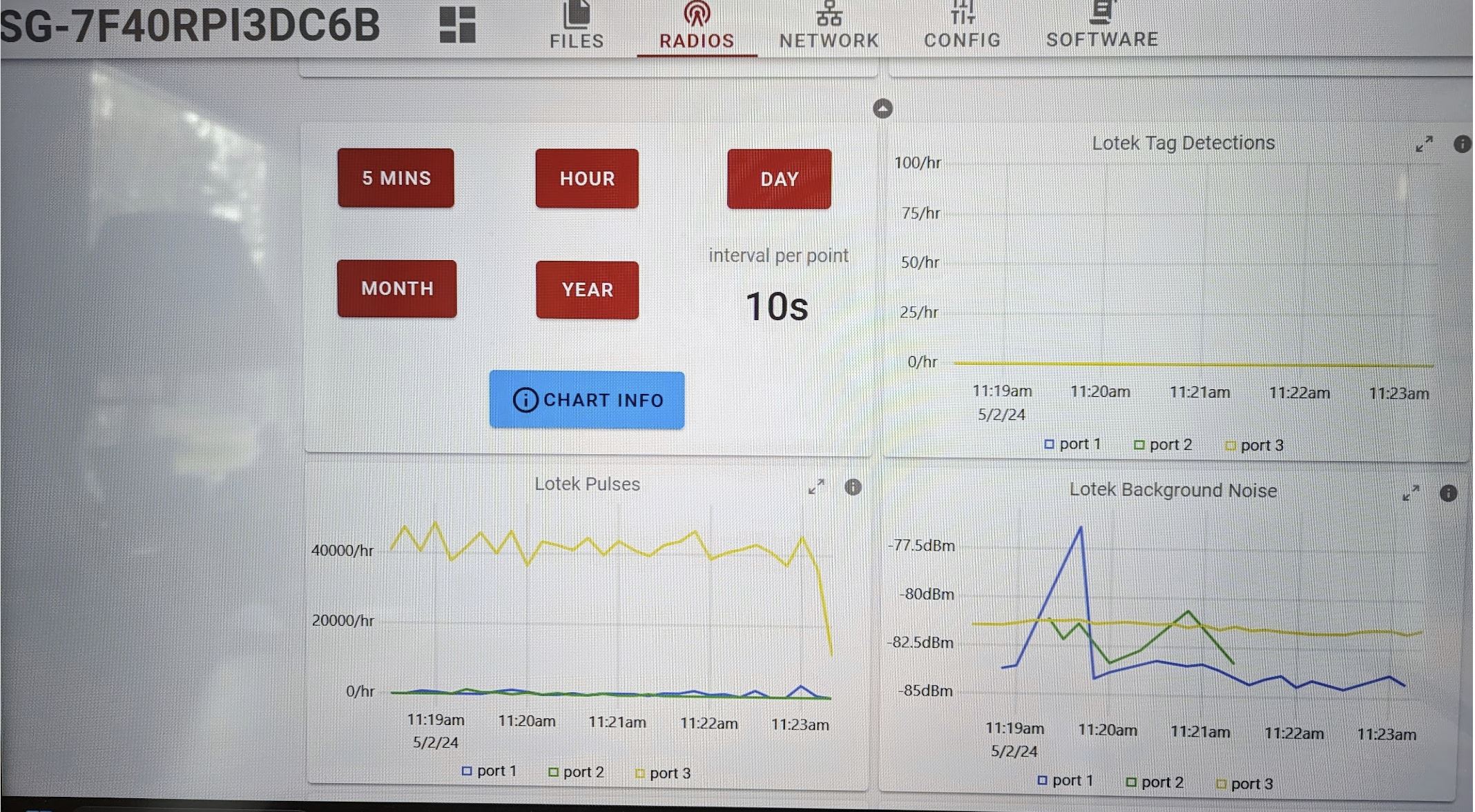
Then on Mar 11th, one antenna on our Sylvan Lake station ( SG-7F40RPI3DC6B) went from 15 000 hits/day to 1 200 000 hits/day. The 1 200 000 hits/day is very consistent day and night. That antenna has a cellular tower about 25 degrees off centre about a mile out. I’m guessing “something” changed on the tower.
First attempt at a fix - Increased the vertical distance between each of three antennas from about 10inches to about three feet. That seemed to reduce the number of false Lotek positives by about 20 to 30%. Better but not great.
Second attempt at a fix - I’ve had very good luck using LNA/filters from Uputronics for a couple other hobbies. Anthony was kind enough to build me two prototypes for the 166MHz band. They’ve just arrived and I hope to install one at the Sylvan Lake station tomorrow and one at Pigeon Lake station on the weekend. Am very much hoping they help. If this experiment can also provide you a bit more information just let me know and I’ll then let you know when and which antenna received the 166MHz preamp/filter.
It would be very nice to see the SNR on the local UI when using test tags. Any chance for this to be added on an upcoming version?
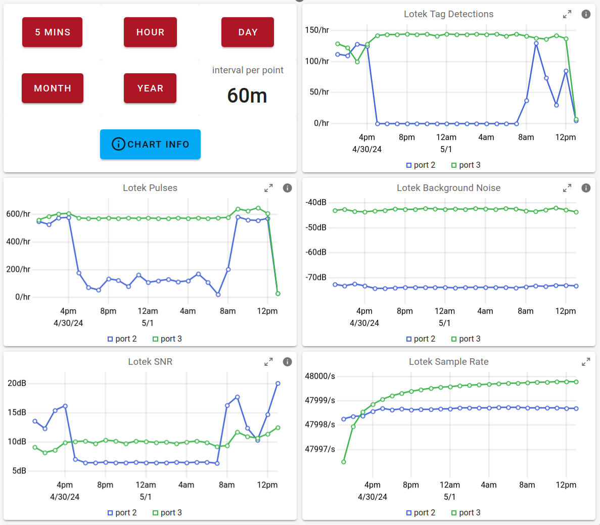
BTW, p2/blue is an FCD and p3/green is an rtl-sdr v4
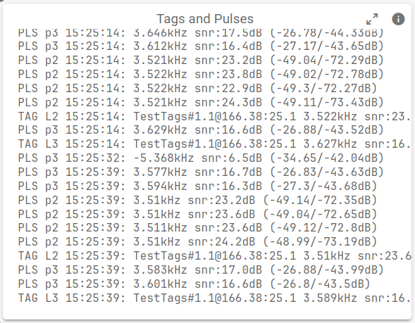
I also updated the text display of pulses and tag detections:
One thing to note: the signal and noise dB values are not absolute (dBm), they’re relative to the range going into the ADC, so post pre-amplifiers and filters and thus the values change with the gain dialed in.
Mark, I suspect local noisy solar power systems may be the noise source, given the diurnal pattern is the noise. Things may have improved when you spread antennas further apart because you made the yagis more directional. The not well documented lore is that the more opposite and close together two yagis are, the more like a big Omni they become.
I have used in my Ham radio experience a device called a cavity filter. they are a mechanical device , no electronic. Cavity Filter are low loss. less than 0.5 db. They are very effective at out of band noise filtering. The problem for 166.MHZ the filter are bout one meter long.
Glenn, thanks for pointing to the LFA, sounds interesting. Do you have links to a more balanced evaluation and how-to-build-and-tune instructions? The blurb you linked to goes from one superlative to the next, which I have a hard time with. In my experience, antenna design is a matter of compromises: you win here and loose there, so I’m sure there are downsides to the LFA too… Of course, maybe they don’t matter…
Cheers!
Thorsten
The cavity filters are great, until you see the size and price tag. If you were to add three of those to a Motus station and provide waterproof housing you’d triple or quadruple the cost of the entire station… That’s the issue.
The Sylvan Lake pre-amp/filter went on about 11:30am MST on Port #3 (yellow). Unfortunately the detections stayed nearly the same. The noise baseline did rise about 16dB (likely from the LNA). I’ve left it going to get some run time. I’m guessing that the noise is something on-band. It’s amazingly consistent at around 40000 hits/hour.
Before
see attached
After
see attached
Thorsten
very much like the UI SNR enhancements you sent. Thanks!
to push my luck, one other item that would be most useful, would it be possible to set up a toggle in the local UI for the 5V bias power from the Funcube Pro +? The Uputronics pre-amp/filter can be powered via an external USB C power supply or from the FunCube Pro + itself. Would save me purchasing a few extra power supplies.
also, I’d be willing to try one of your filters at Sylvan Lake if you’d like.
Will try the other Uputronics 166MHz pre-amp/filter at Pigeon Lake likely Saturday. Thanks for the suggestion but I don’t think it’s solar panel issue, sometimes the worst peak is at 4am, not often but sometimes. The noise varies a lot in intensity, unlike the Sylvan Lake noise, which is very consistent.
I remember those cavity filters from my basic HAM course. Elegant but a bit expensive. Will see how the other filters work.
So far I have not found down sides the the FLA. I had planned to build a LFA antenna for 166.380 and after I add up the cost of the parts it was much more than ordering one from https://www.innovantennas.com the cost was $280 USD shipping was over $ 100 USD. It was a special order so a few weeks lead time. The problem with building your own antennas is that most people do not have the specially tools and the electronic test equipment needed.
Now the 434HMZ is in stock at $125 USD again the problem is the shipping. These antennas are of superior quality.
I also suggest to use a high quality coax like LMR400 beware full of some cheap intimation. Cheap coax can pickup noise. It can act as an antenna. I also use a ferrite core noise suppressor on the coax near the feed point of the antenna. They are cheap but the must use the correct one for the frequencies. Also high quality connectors are important.
We ham use specialized software for digital signal receiving. The problem with this software it would not work with the $166.380 pulse code modulation. The code looks like noise to the noise blanking and digital signal processing the ham software use. it does wok with the CTT FSK frequency shift keying.
I had a noise problem on 166.380 that turn out to be an exhaust fan about 25 feet from my receiver.
Now about cavity filters. When I win the lottery I will build the ultimate Motus station using cavity filter with with six 434 MHZ five LFA yagi and on high gain vertical, five 166.380 mhz yagi and one high gain vertical with LMR500 yes LMR500 coax on a high tower.
So much for my rant. Just my opinion and as said your mileage may very. I can be contacted at pollockg@cox.net Glenn
Will take a look at those LFA’s, I know very little about them.
Indeed, the stations use LMR400 with good connectors.
I have a spare “small” 166 yagi, so the next step for Sylvan Lake will be to go out with it and an AirSpy SDR and see if we can localize the noise source. The noise is very consistent and only on one of three 166 antennas.
That would be a very nice “lottery” station. You might need to check with Thorsten to see if the Sensorgnome can handle that many channels! ;)
Re: Bias-T, you can enable the Bias-T power on FCDs by adding a section to /etc/sensorgnome/acquisition.json, specifically in the funcubeProPlus plan in the devParams section, add something like:
beware of the trailing commas after } in json: no comma before an outer closing }
You can also enable the boas tee via cmdline. Run fcd -l to get the list of FCDs, look at the enum values, then run fcd -w 0x10 1 to enable and fcd -w 0x10 0 to disable, fcd -r 0x10 reads the current value.
I have not tested the above, only read the code ;-) Lemme know if it doesn’t work.
Warning: enabling the Bias-T in the acquisition file enables it for all FCDs, so ensure you do not have an electrically shorted antenna on any.
I will add something equivalent for rtl-sdr.
I don’t know what to think about a UI toggle 'cause inadvertently toggling that with an electrically short antenna could burn something out
Thanks for that Thorsten. You’ve inspired me to dig around a bit. I’m leaning toward the command line instruction, would definitely need the function to be FCD specific.
Lol, i had the same thought, would a UI toggle be “too easy” and eventually get me on a short circuit. Likely. :)
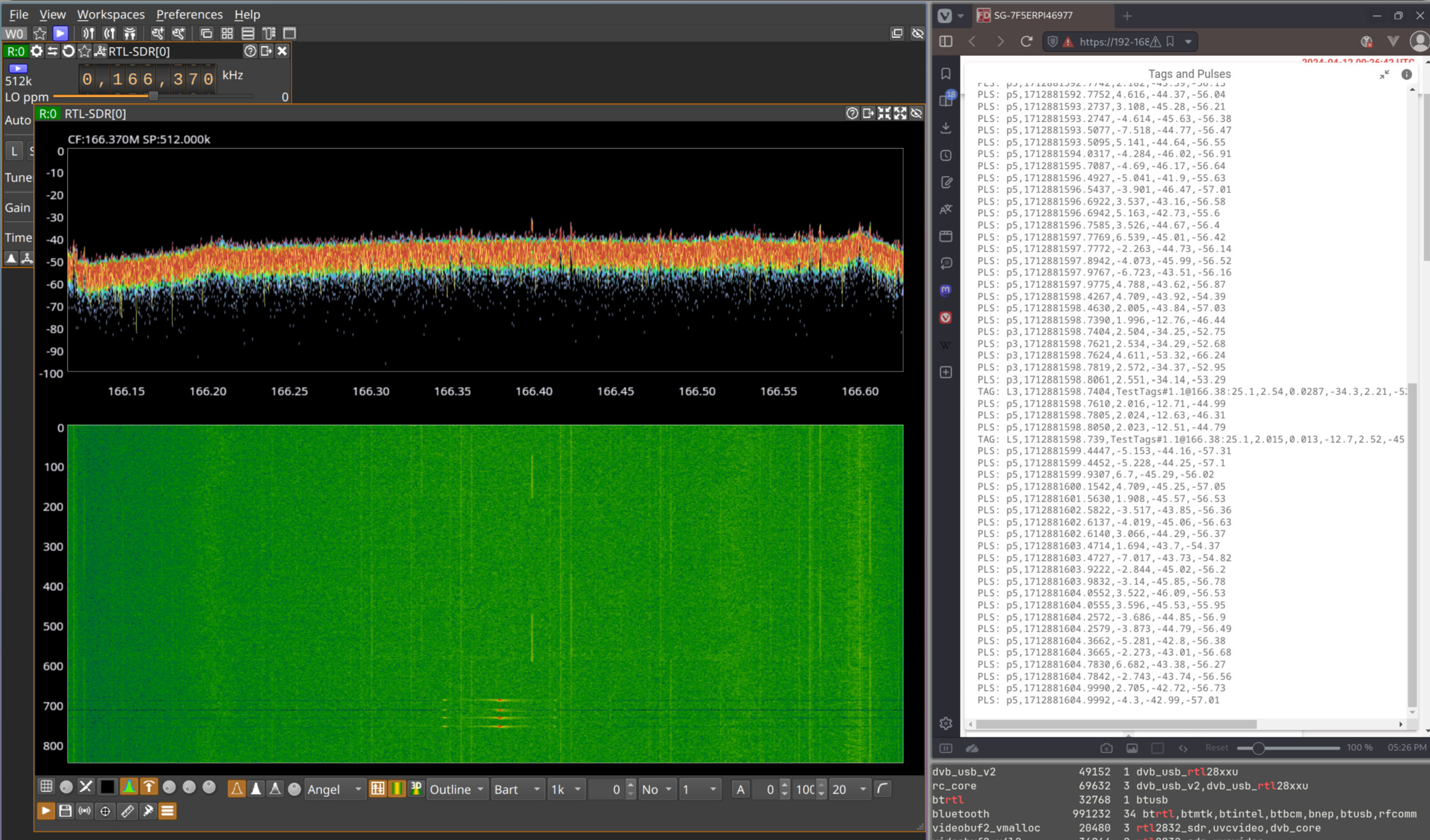
I’m curious what you find out with the Airspy SDR. I spent some time looking at an rtlsdr attached to the antenna I have pointed towards town and I kind’a concluded that I couldn’t see anything of interest, despite the fact that it gets a fair number of spurious pulses. I first tried to see the transmissions of my test tag to have some form of baseline/reference. That proved to be extremely difficult. I could only manage using SDRangel, none of the other programs could show me the pulses. (The UI of SDRangel is, let’s say, “quite something”…) This is what I managed to capture:
In the waterfall display, the tag transmission is shown as the 4 small vertically aligned red dots. The other streaks are other stuff. Each dot is ~2.5 milliseconds tall so they zip through that waterfall display in a fraction of a second. a real test to how fast I could hit the pause button! You’ll notice that the spectrum view at the top doesn’t show anything for the tag. The right-hand display has the pulses which far outnumber actual tag detections.
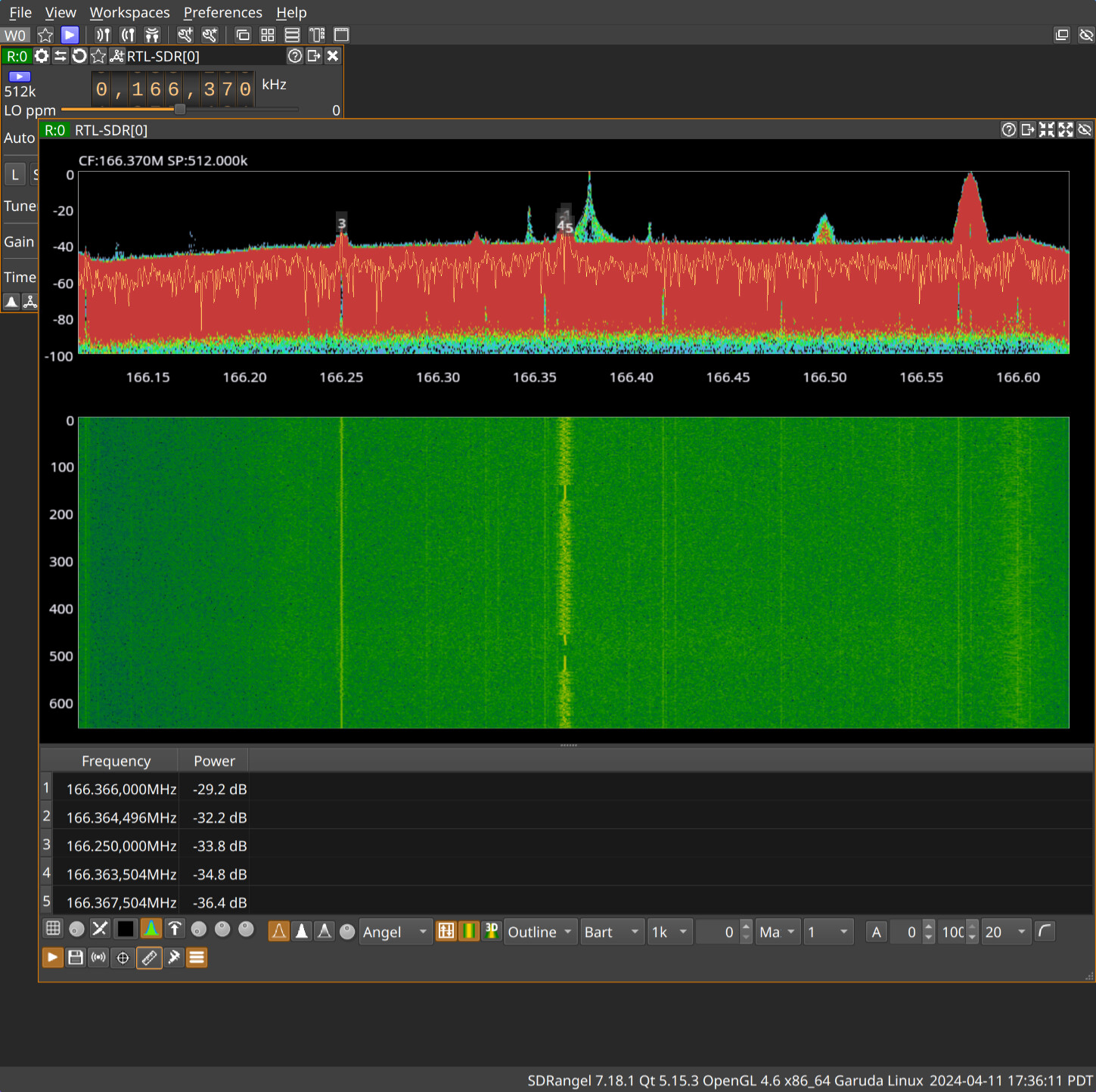
With some more tweaking of “max hold” I can get the tag transmissions into the spectrogram:
The tag transmissions are the “Eiffel tower” in the middle. There is what looks like an FSK signal in the waterfall right next to it (166.363 Mhz) and somethings else “further away” around 166.575Mhz.
I found all this “interesting” but I could not correlate anything with the noise pulses detected. Looking at the spectrogram you might shout out “that’s it! something is transmitting really close by” but it was intermittent and not correlated with noise pulses. So I kind’a concluded that as interesting and challenging as these images were to capture they were not helping me with determining the source/cause of the noise pulses. I hope your situation will bring up something more useful!
I just built 2 sensorgnomes using the Nooelec RTL-SDR v5 SDR - NESDR Smart HF/VHF/UHF (100kHz-1.75GHz). now I did see that V4 was compatible I assumed V5 would work too. but after seeing this thread I thought I would check to see if there was any info on compatibility. I am trying to find someone that has some tags that will allow me to verify it but that is still in the works. Any information would be helpful.
Please be aware that while I have made the changes necessary for rtl-sdr.com v4 dongles in the codebase I have not released a build with them. I’ve been sick and everything has been slow…
Be careful about mixing v4/v5/vN. There is no company that owns “rtl-sdr”: it’s like saying “a cell phone”, Google’s cell phone version numbers have nothing to do with Samsung’s. The “v4” dongles we talked about in this thread are made by rtl-sdr.com (a company) and the “NESDR SMArt v5” you mention is made by Nooelec – a different company.
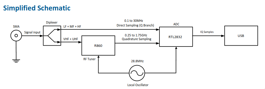
The rtl-sdr.com v4 uses the multiple inputs of the out-of-production R828D tuner to support a couple of broad input filters. The correct filter has to be chosen by the software for this to work. This required an enhancement of the ubiquitous librtlsdr library and this is why it’s not instantly compatible.
I’m not seeing anything in the Nooelec NESDR SMArt v5 that would cause an incompatibility. It does add a diplexer at the input to allow for direct sampling of HF frequencies (which is of no use to Motus) and I wonder what the impact on higher frequencies is. Any component added to the RF input introduces noise and signal-to-noise is the main disadvantage of rtl-sdrs vs. FCDs, so I’d tread with caution.